![]()
Planning agency: International Highway Construction Agency
Implementing agency: Far East Development Co., Ltd.
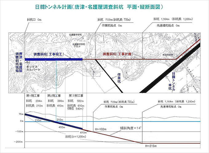
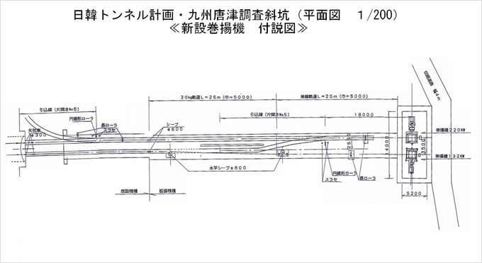
After roughly five years since the start of construction of the exploration incline, construction of the first and second phases of the incline is nearly complete, and the project is now approaching the stage for replacing the temporary equipment as originally planned. While the capacity of the temporary equipment for the second phase, particularly the hoisting winches, was designed for an excavation length of approximately 500 meters, the capacity required for the third and subsequent phases of construction will be increased to accommodate the 1,410-meter design incline.
Other improvements include the addition of additional power receiving equipment and expansion of water supply, drainage, air supply, and ventilation systems. Furthermore, as construction continues, new mud treatment facilities and injection equipment will be required. However, if excavation is required to continue for the time being, this is likely possible with only minor modifications to the hoisting winch power receiving equipment and minor additions to other equipment.
The equipment (PUC-20T) for the first 500m of the second phase is as shown below, but as the excavation length increases from the third phase onwards, the equipment specifications will vary significantly.
An overview is given below.
| 2-1 Basic conditions |
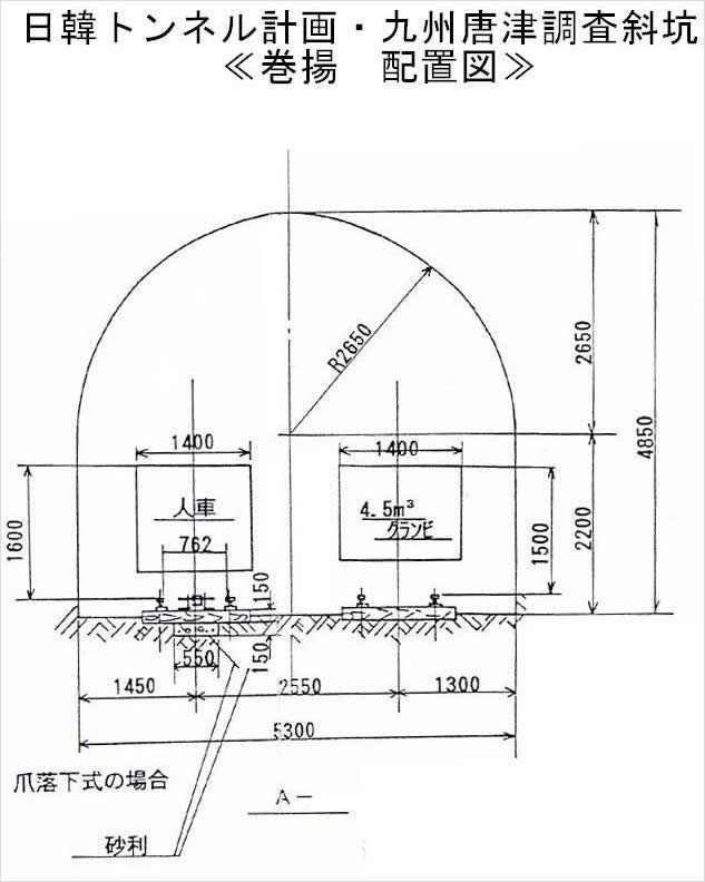
Tunnel slope angle:☆ θ=14°02′ Diagonal shaft length:☆ L¹=1400m Lifting distance:☆ L²=1500m Transport weight: mine car 2700kgf/car x 2 cars = 5400kgf Car contents: 1.7tf/m³ x 4.3m³ x 2 = 15,300kgf Pedestrian car: 12-seater Hoisting speed:☆ υ=150m/min The ☆ mark is common to both the mine cart and the man cart. |
||
|---|---|---|---|
| 2-2 Equipment Specifications |
2-2-1 mine car hoist |
1) Loading conditions |
W¹ Weight of mine car 2700kgf x 2 = 5400kgf Load 1700kgf/m³ x 4.5m³/car = 15300kgf ∴W¹ = 5400 + 15300 = 20700kgf W² Weight of wire rope 2.59kg/m x 1500 = 3885kgf |
| 2) Rope tension |
P=W¹(sinθ+μcosθ)+W²(sinθ+μ′cosθ)=20700(sin14°02′+1/60cos14°02′)+3885(sin14°02′+1/10cos14°02′)=5430+1320=6750≒6800kgf . |
||
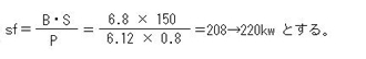
| 3) motor output |
 |
||
| 4) Rope Safety Factor |
 Rope diameter: φ25 (tough rope) Rope diameter: φ25 (tough rope)Breaking strength: BS = 50.1 tf |
||
| 5) driving |
The operation will be manual from the winding room. However, for certain sections (pit entrance to bottom), the operation will automatically accelerate → full speed → decelerate → stop. Since the face changes as the excavation progresses, the stop switch and overshoot switch will be relocated. |
||
| 2-2-2 Handcart hoist | 1) Loading conditions |
W1 Weight of man/vehicle: 7160kgf (including hanging hardware) W2 Weight of wire rope: 1.99 x 1500m = 2985 kgf |
|
| 2) Rope tension |
P=W¹(sinθ+μcosθ)+W²(sinθ+μ′cosθ)=2070+1013=3083≒3100kgf. | ||
| 3) motor output |
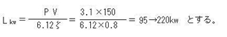 |
||
| 4) Rope Safety Factor |
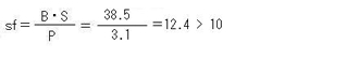 Rope diameter: φ22 (tough rope) Rope diameter: φ22 (tough rope)Breaking strength: BS = 38.5 tf |
||
| 5) driving |
Basically, it is the same as a mine car hoist. |
||
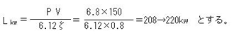
| 1) Electric capacity | ①Compressor | 150kw | |
|---|---|---|---|
| ② Repair shop | 20kw | ||
| ③ Blower | 60kw x 2 = 120kw | ||
| ④Hoisting machine | A) | 220kw (for waste disposal) | |
| B) | 110kw (for passenger cars) | ||
| ⑤Plant equipment | 22kw | ||
| ⑥Spraying machine | 11kw | ||
| ⑦Jumbo drill | 220kw | ||
| 8. Water pump | 15kw | ||
| 9. Lighting power | 40kw | ||
| ⑩Other | 20kw | ||
| total | 948kw | ||
The total power used in this project is 948 kW, but the plant equipment (22 kW) and the sprayer (15 kW) will not be used during excavation. Also, the jumbo drill and the tailings hoist will not be used at the same time, so a contracted power of 700 kW is considered sufficient.
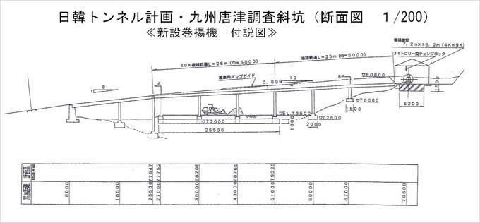
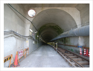
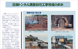
*Construction completed, with one track removed
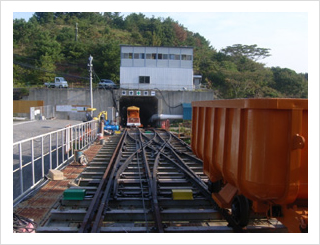
*The third phase construction site (the entrance to the inclined shaft is in the center)
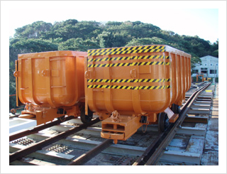
* There are two muck transport vehicles, one on top and one on bottom.
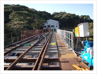
* The white building is where the winch is installed.
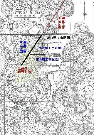
Nagoya inclined shaft investigation site for the Japan-Korea Tunnel
Overview of the Japan-Korea Tunnel
![]()